
In this use case, the Raspberry Pi requires at least four connections:
- A 5V 2A (or so) main power source,
- USB connection to the Arduino Nano,
- audio output from the 3.5mm stereo jack, and
- an external USB connector for playing music from USB mass storage.

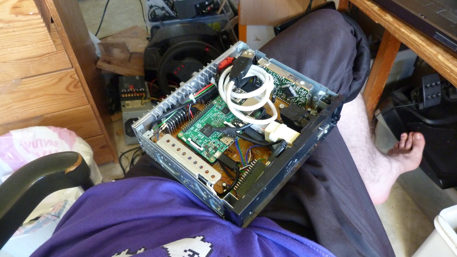
Oh... how do you attach it, you ask? I used scrap polyethylene plastic, a small-ish wood saw, very small screws (picked up from disassembled pastic crap) and a small enough drill to add a second "layer" on top of the bottom PCB and attach the Pi and other stuff onto it.
5V Power source
What we have available to us is automotive battery voltage, usually being anything between 11 to 15 volts, sometimes down to 0 volts, and sometimes up to basically anything, in the case of eg. a loose alternator connector or whatnot. Basically, this is able to kill our device in rare circumstances unless our device has protection circuitry to tolerate something like 230VAC.Well, I'm lazy, but not stupid. I happen to have a couple of cheap DC-DC switch mode power supplies from ebay that handle up to 60V input, 3A output and can be configured to put out 5 volts. One of these will be fine enough here - if it breaks, it breaks, and if it breaks our Raspberry Pi, 100€ lost at tops.
Now, the Nano has to be able to switch this power on and off. It can be done by desoldering and lifting up the ON/OFF leg of the LM2596HV regulator IC and applying 0 or 5 volts from the Nano...
...except that if we did that, the Pi+Nano combination would end up in an infinite restart loop, because the Nano always restarts when the USB device is opened in Linux, causing an undefined state on the ON/OFF pin while the Nano is booting up.
What we can do is add a capacitor from the ON/OFF pin to ground, and add a resistor in series with the control wire coming from the Nano. This way the ON/OFF pin state will stay the same long enough while the Nano restarts when our software running in Linux is opening the USB virtual serial port in order to talk to the Nano.
Now just add a lot of insulation tape and cram that switch mode power supply somewhere inside the head unit...
USB connection to Arduino Nano
This is just a shortened USB cable. Nothing to see here. Use heat-shrink tubing for insulation so that you'll never have to come back to it.Audio output from the 3.5mm stereo jack
There are a few places on the head unit PCB we could insert this signal into, but the one that makes the most sense is the CD-ROM drive signal lines; their input side is completely disconnected as the CD-ROM module was removed, and the wires coming from the 3.5mm stereo jack can be soldered directly onto those signals. The signal voltage levels are probably close enough. |
| New layer of plastic on top of the PCB and the audio input cable hanging from the PCB. |
An external USB connector
This is more of a mechanical thing. You need a short USB A male-female cable, a file, a sharp knife, some spare pieces of plastic or wood or something, a drill, screws, some zip ties and super glue and whatever you are comfortable with to attach the female end to poke through the front panel enough to hold a USB dongle.You probably also want an external RJ45 ethernet connector for connecting using SSH for debugging and moving files around and whatnot. It just adds to the physical torture. A female-to-female adapter and a very short cable is handy.
 |
| Building a solid base from plastic for super gluing and zip-tieing the USB female connector onto, very finely positioned to poke out from the original CD-ROM slot. |
 |
| The CD-ROM slot was modified to house the female USB A connector using a knife and a file. The front panel still comes off as originally designed. |
Blogin hallinnoija on poistanut tämän kommentin.
VastaaPoista